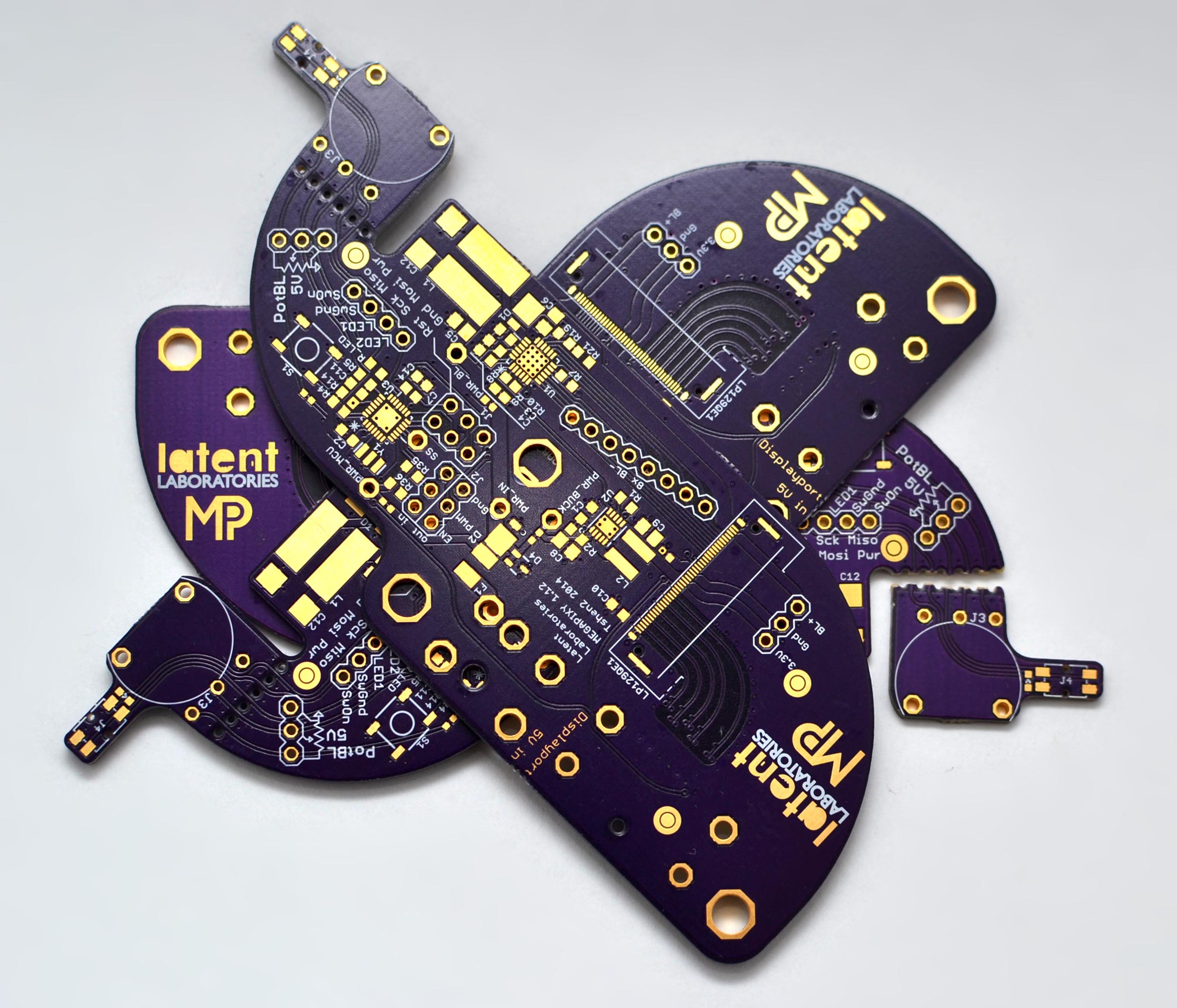
i am happy to announce that the Megapixy design files are now available online for your viewing/modding/hacking pleasure.
this took awhile. it turns out, when many of my design files are over a year old, i need quite a bit of time to organize them!
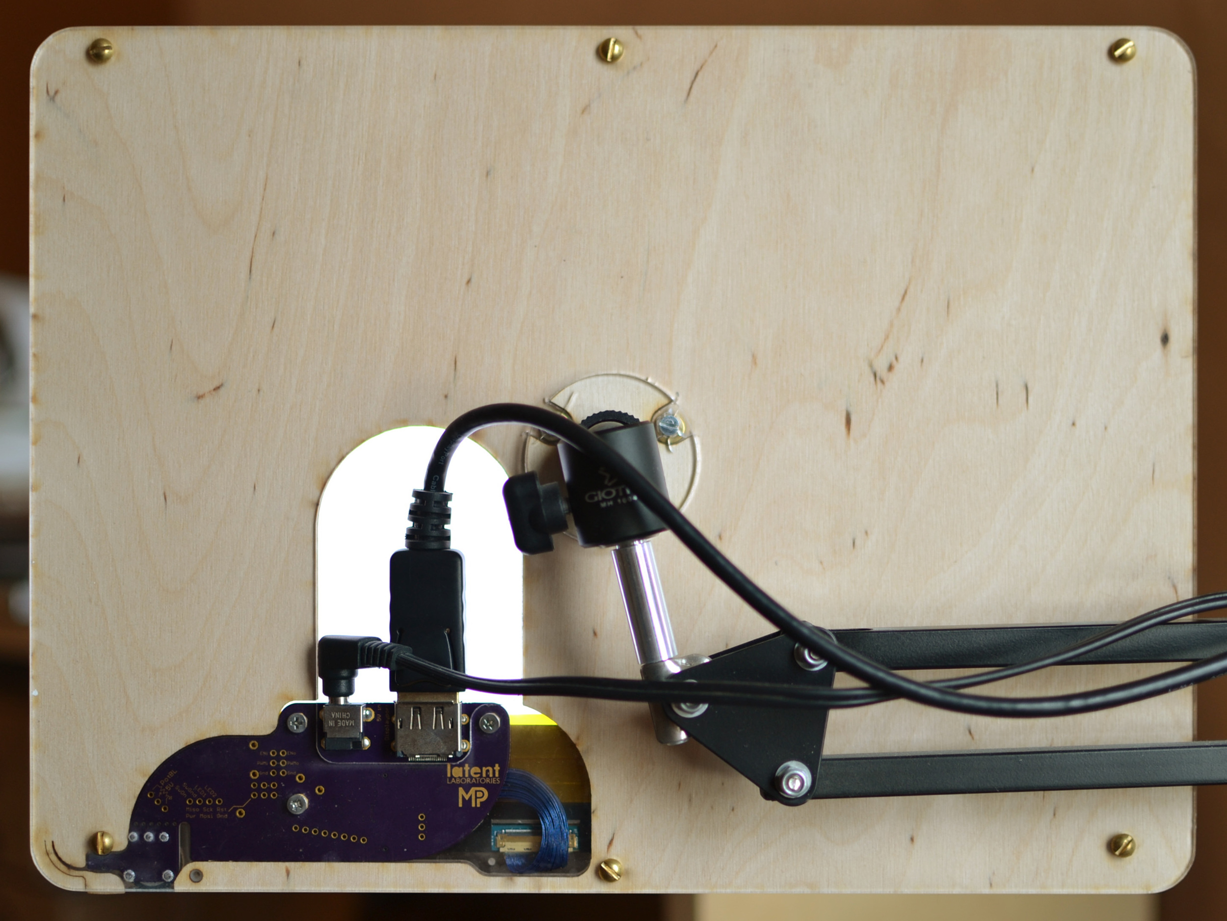
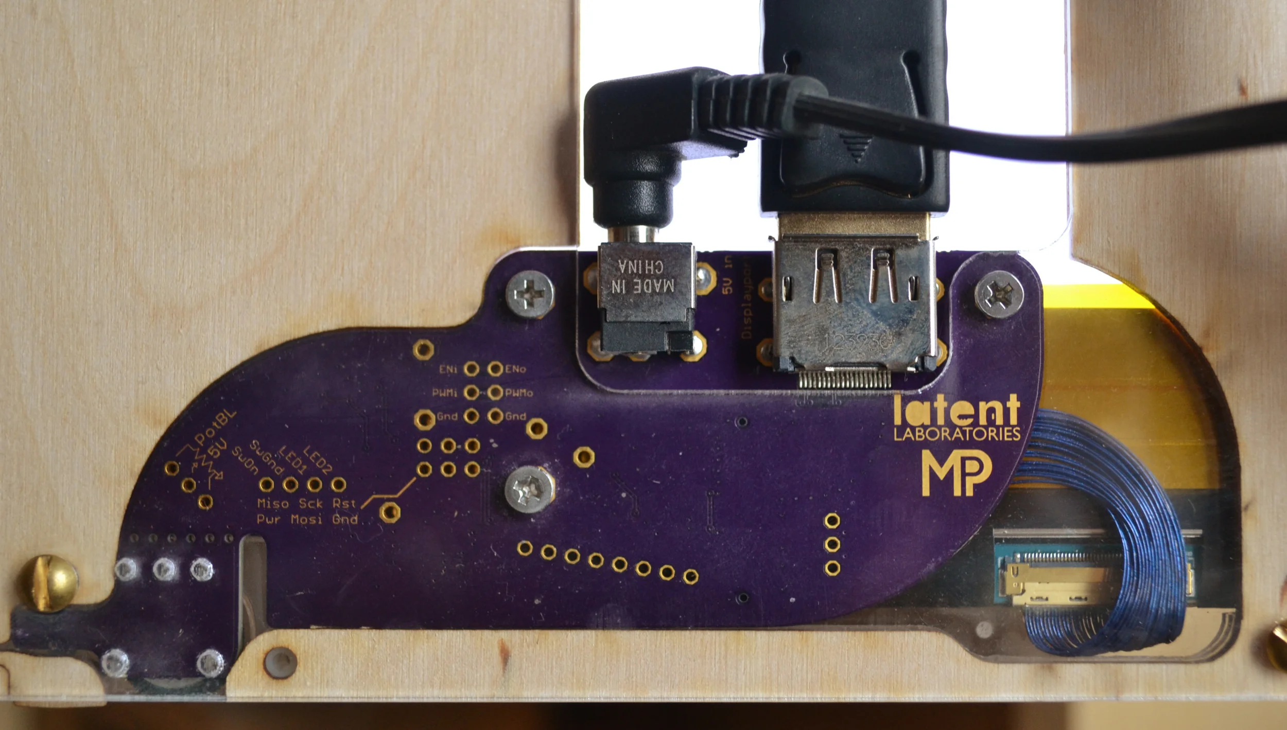
Megapixy is an adventure in sourcing parts. you will probably struggle to find the PCB receptacle for the IPEX micro-coaxial cable, as well as the cable itself. i have spares! contact me and i can help you.
have a great day :)
Tshen2 2015