
let's revisit that photo from my last post:

why is the bottom-right footprint not like the others?
in my last post, i got the Retina iPad LCD panel working. but it was buggy & small & rather underwhelming.
although! that is just one LCD panel in a world full of LCD panels. my approach should work with any panel which communicates through embedded Displayport (eDP). what other eDP panels are easily obtained, which are more worthwhile to hack into?
bear in mind that this is 2013, a year where only Apple computers have screens worth giving a damn about.
except one other computer.
the Chromebook Pixel.
running a stunted operating system on beautiful hardware, the Chromebook Pixel is a mixed bag.
but that screen! it's glorious.
2560x1700 pixels, 13 inches across. that's 4.3 million pixels at 239 pixels per inch. 3:2 aspect ratio. massive contrast, huge viewing angles, colors out to infinity. it's IPS at its best.
what's more - unlike the Retina Macbook screens, the datasheet is available and the price is right. but no one else has done it - why? let's look at the datasheet:

apparently it's got some whacko connector on there - an IPEX 20474-040E-12. how do you connect to that?
i'm guessing that this is where most hackers get stuck. but i really, really like screens, so i keep going.
so i randomly ping LCD cable manufacturers on Alibaba. they're all in China.
has anyone heard of the 20473-040T-10? can you take two of those and build me a 40-wide micro-coaxial array? everyone wants this, right?

ok, i made that in Powerpoint. can i has cables?
they say i must pay for cables. but how? ESCROW?
no, not ESCROW! the correct answer is Paypal.
Paypal is how you send money to cable people in China.

omg cables!

omg LCD with cables!

ding!
and does the crude test board work?
yes it does!
even with long cables!
so obviously the Chromebook Pixel LCD panel is the way to go. and it's big enough that people might actually use it at a desk. so let's jettison all the internal-battery stuff, and focus on making a really solid wall-powered screen.
this is when i actually start making the thing.
i'd like to point out: at this point in my career, i had no idea what i was doing.
i was supposed to design a circuit board? and some kind of chassis? to hold the screen in place?

i am drawing things! with computers!
i'll ask a friend to lasercut the frame, because idk lasers.
and idk mechanical design either. so instead of an enclosed frame, let's make a crappy rollcage with a front bezel and a back panel. but how to hold the panel in place?
let's hold the panel with a 'lip' made from standoffs & Nylon washers:

and now, a PCB!
i call it the 'L' board.

schematic of 'L' board
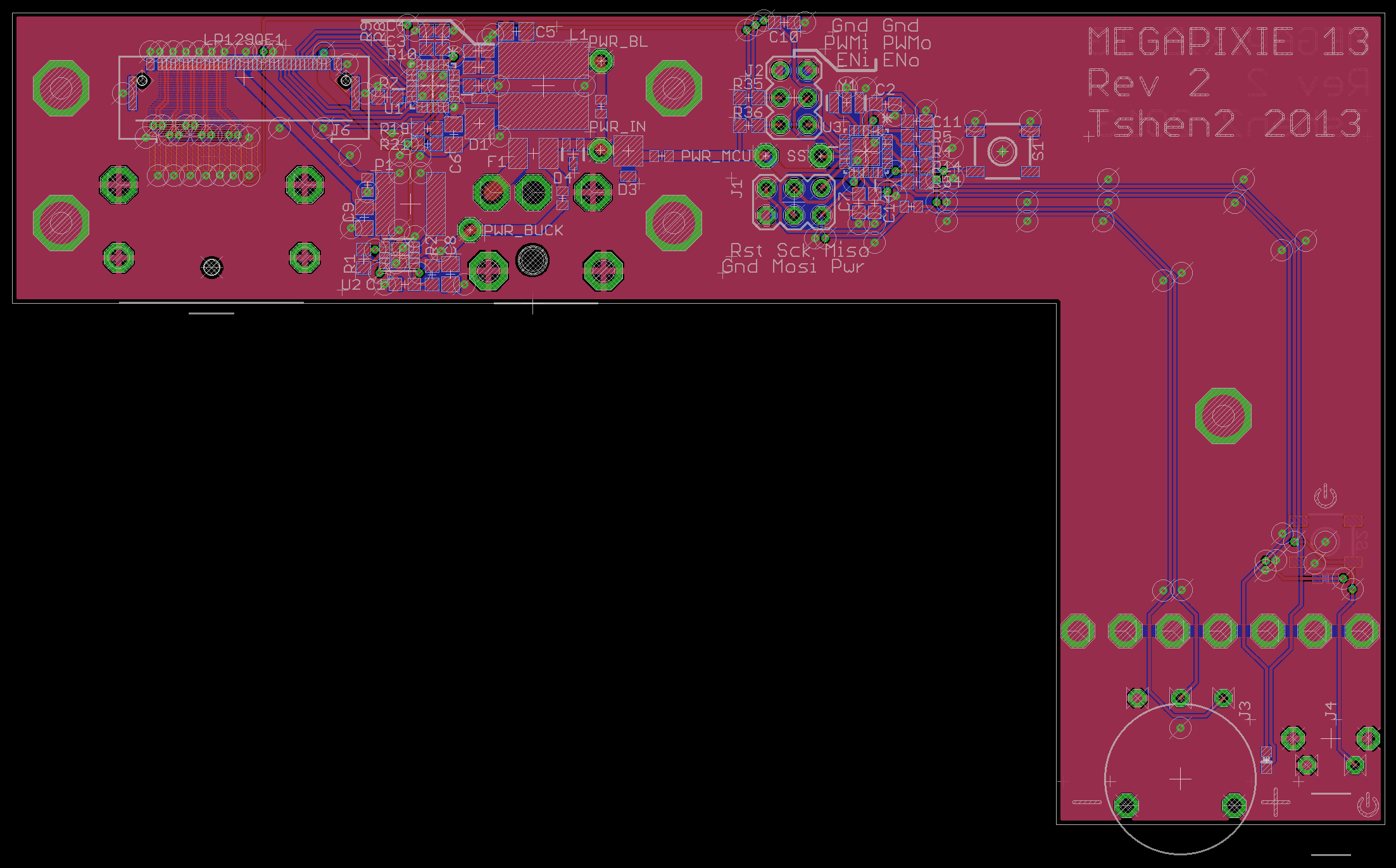
layout of 'L' board

'L' board, front view

'L' board, back view
as per my war on identical rows of buttons, there are only two controls:
- an on/off switch
- a brightness dial
it's obvious, even in the dark. a dial is ideal for adjusting brightness, and doesn't feel like a button at all.
but this board is horribly flawed, because the Displayport cable and delicate LCD cable end up bumping into each other.

not so good!
why is this happening? because the 'L' board is a crude extension of my test board. i tried to keep my high-speed traces as short as possible on the test board, which created that awkward cable collision.
so i have to make a new test board, to put some distance between those cable connectors.
time for more shotgun engineering!

boom!

the lowest board worked the best.
now there's a 90-degree bend between connectors to prevent cable collisions! and with this, i built the 'comma' board.

schematic of 'comma' board

layout of 'comma' board

'comma' board, front

'comma' board, back
did you notice all those holes at the neck of the comma? they let you snap off the on/off button and brightness dial.
this lets you build a mega-screen with multiple LCD panels and control boards. you only need controls on one board, which communicates with the rest.
i also began doing basic mechanical drawings in Eagle.

mechanical drawing, showing position of control board relative to LCD panel

lasercut chassis with 'comma' board, front view

lasercut chassis with 'comma' board, back view. note the 1/4-20 tripod screw mount.

on/off button and brightness dial, coplanar view

on/off button and brightness dial, angled view
as compared to my first disaster, it's much lighter, with a more even weight distribution. this means i can mount it on a flexible boom arm instead of a heavy tripod.


clampy!

chassis mounted on boom arm.

hello!
i guess it's.. basically functional? but i'm not satisfied.
the LCD panel is held in place by a 'lip' mount below the bezel. this puts uneven stresses on the panel, causing backlight bleed.
and it's ugly.
my work is not done.
next time: Megapixy logo, Giger board, the beginnings of beauty.
Tshen2 2013