let's detour into visual design - did you notice this on the previous update?

it's the Megapixy logo!
i like Megapixy, and i like making logos. go figure.
in the infinite possibility space of logo (and not-logo) design, some reason must be provided for why anything looks like anything. the Megapixy logo exists because:
- Megapixy uses the embedded Displayport video interface.
- Megapixy has the same 3:2 aspect ratio as the Chromebook Pixel.
with regards to 1, there's a little homage to the Displayport logo:

as for 2, the Megapixy logo also has a 3:2 ratio.

now back to engineering :D
hybrid PWM/PFM brightness control
brightness control should be easy, right? nope.
there's an ATtiny microcontroller on the 'comma' board which reads the brightness dial. the microcontroller creates a PWM signal which gates the backlight driver. it looks like this:

block diagram of Megapixy brightness control (first try).
some simple measures were taken to reduce electronic noise:
- a capacitor at the input of the microcontroller's ADC.
- a 128-sample moving average filter.
- a 2-LSB hysteresis filter, to reject small (noise-related) brightness changes.
and then, an interesting bug. when the screen was on, i could hear a tiny whining sound!
and to explain that, i'll have to talk about PWM.

cartoon of pulse-width modulation (PWM)
pulse-width modulation (PWM) means controlling something with a series of on/off pulses. the perceived 'on-ness' (e.g. backlight brightness) is based on the fraction of time when the device is 'on'. this fraction is called the duty cycle. the on/off pattern repeats with a fixed frequency.
the backlight driver's on/off pulses were a PWM running at 500Hz. i was powering the Megapixy with a cheap 5V power supply, which was now having to supply more & less power on a 500Hz cycle. this caused my power supply to buzz audibly at 500Hz - the so-called 'coil noise'. how could i fix this?
i could make the sound inaudible by increasing the PWM frequency from 500Hz (repeating every 2ms) to 20kHz (repeating every 0.05ms).
inaudible to humans, anyway. some dogs might notice.
the problem is, the higher your PWM frequency, the shorter your 'on' pulses:
- a 20% duty cycle at 500Hz requires 0.4ms 'on' pulses.
- a 20% duty cycle at 20kHz requires 0.01ms 'on' pulses.
during each 'on' pulse, the backlight driver has to turn on and pump up the backlight voltage. this process takes about 0.01ms. if the backlight driver doesn't have enough time to turn on, it shuts down completely until the circuit is reset. with a 20kHz PWM, this places a 20% minimum duty cycle on my backlight brightness control.
why is this a problem? because people like their screens to be really dim at night!
a 20% to 100% brightness adjustment isn't good enough. so what can i do?
there's this other thing called pulse-frequency modulation (PFM):

cartoon of pulse-frequency modulation (PFM)
in PFM, the duration of each 'on' pulse is always the same. to reduce the duty cycle, you can increase the time between 'on' pulses. at very low duty cycles, you will have large gaps between each 'on' pulse, which means a lower (and perhaps audible) frequency.
but PFM is still worthwhile because you can reach a lower duty cycle (brightness) without shortening the 'on' pulse. this gives the backlight enough time to turn on, even at very low brightness settings.
neither PWM or PFM does exactly what i want, but can i combine them to solve my problem?
- above 25% brightness, i could use PWM.
- below 25% brightness, i would automatically switch to PFM
the power supply might make sounds in the lowest brightness settings, but at least i would have lower brightness settings.

partitioning of brightness control into smoothly-transitioned PWM & PFM.
getting a smooth transition requires a teeny bit of math.

featuring a random notebook from a random hotel.
the net result is a brightness dial which adjusts from 100% (silent) to 2% (almost silent).

cartoon of hybrid PWM/PFM brightness control.
that's enough about brightness control!
i'm still not satisfied
with the Megapixy. why? let me count the ways.
- the 'comma' board looks stupid and wastes space. it's a sure sign that i haven't constrained it enough.
- the Displayport cable sticks out at a stupid angle, like an awkward elbow. it should attach neatly, next to the screw mount.
- the chassis is stupid. the wood warps when wet, the design wastes material, and the bezel bends under my fingers when i hold it.
- the LCD panel is mounted unevenly, causing backlight bleed.
let's address 1. why does the 'comma' board waste space?
- it stretches left to reach the LCD cable, as the cable comes straight up from the panel.
- it stretches right to reach (and house) the on/off switch & brightness dial.
- it requires too much z-height, because the tallest components (backlight capacitor & inductor) must fit under the screen.

to fix 2, i want to reposition the Displayport video connector, so i definitely have to move the LCD cable connector. i might as well move it closer to the controls, to reduce board size.
how can i make the cable reach its connector's new position? i can bend it. duh.
i can also move the tallest components out from under the screen. it saves a precious millimeter.

this was around the time that H.R. Giger died, which made me sad. being in a Giger-ish state of mind, i ended up making a PCB which looks.. strangely organic.
i call it the Giger board.

schematic of Giger board.
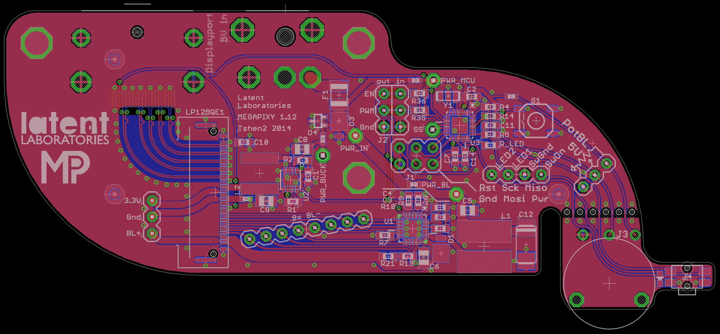
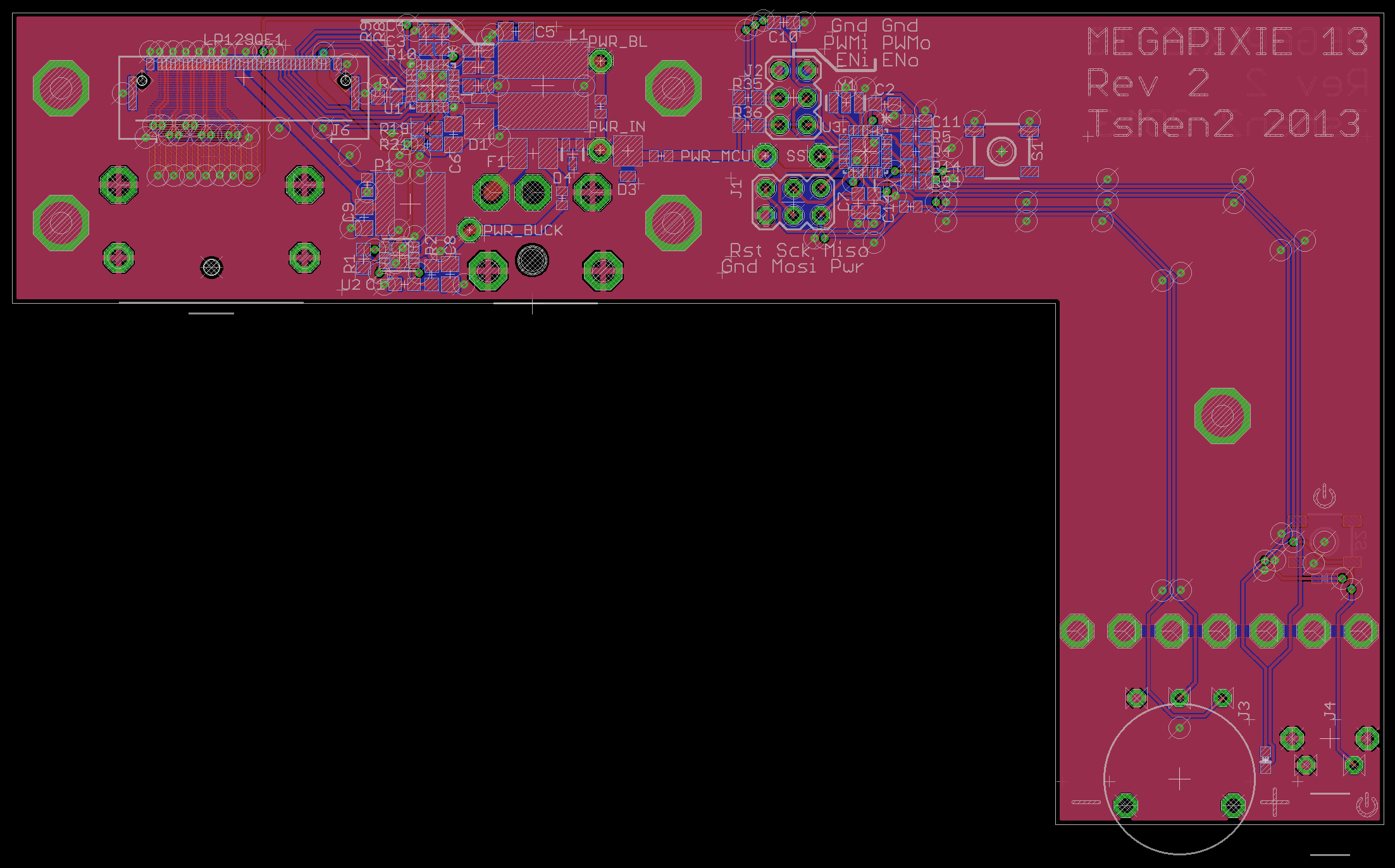
layout of Giger board.

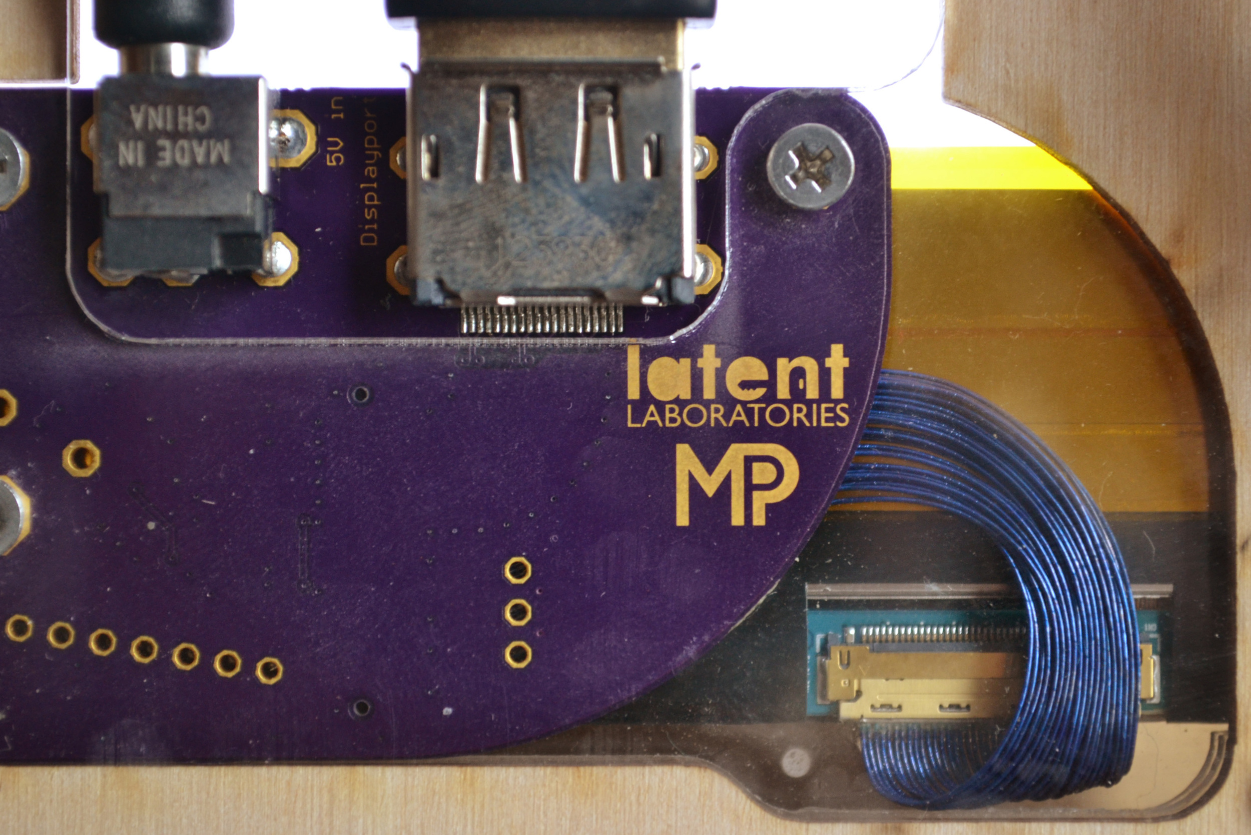
Giger board, front.

Giger board, back.

assembled Giger board in chassis (TBA).
LCD cable, bent to reach new connector position.

backlight capacitor & inductor, no longer under the screen. the on/off switch cover has a living hinge.
the result is a smaller, denser, more beautiful board which scratches my artistic itch.
but there's still two problems to solve!
- the chassis is stupid. the wood warps when wet, the design wastes material, and the bezel bends under my fingers when i hold it.
- the LCD panel is mounted unevenly, causing backlight bleed.
and that's what we'll talk about next time.
next update: fancy chassis design, lasers, lasers, lasers.
Tshen2 2014